
We evaluate the requirements of the metal injection molding process at the design stage; we optimize part geometry, wall thickness, shrinkage, tool design and sintering conditions together.
Before manufacturing a part, we understand its story. Application conditions, loading conditions, functional expectations and production volume... We put all these variables on the design table and select the most suitable process and material combination together.
This approach reduces costly prototype iterations, shortens time-to-market and ensures that the final part is optimal both functionally and economically.
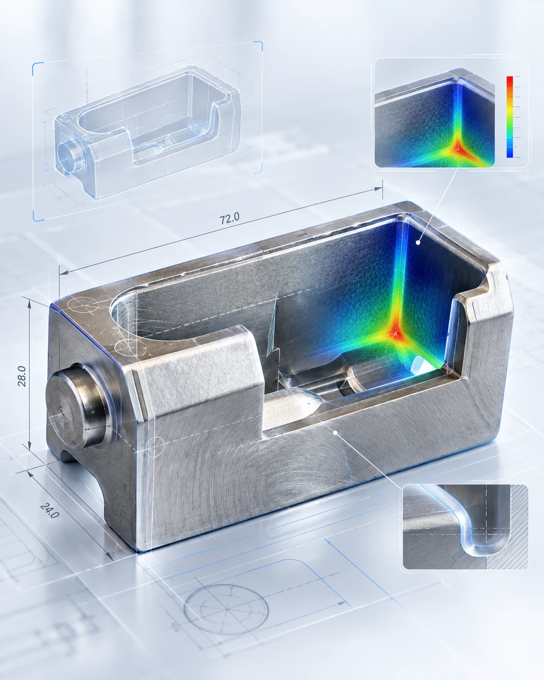
Complex geometries · Thin sections · Small details
Holes and channels · Undercut areas
Wall thickness distribution · Abrupt section changes
Sink/void risk in thick areas · Filling behavior
Appropriate draft design for safe ejection of the part from the tool.
Through holes · Blind holes
Diameter ratios · Core/pin design
Optimization to reduce unnecessary thickness and ensure proper sintering.
Because MIM parts shrink significantly during sintering, controlled shrinkage compensation is applied in tool design.
The fundamental rules to observe at the design stage directly affect cost and quality. The table below summarizes the most critical limits on a part basis.
We evaluate the design and production requirements based on your part's 3D CAD model. By analyzing geometry, dimensions, tolerances and critical functional areas, we establish a suitable starting point for the MIM process.
Focus: Geometry & FunctionWe technically assess whether the part can be manufactured with MIM technology. We consider geometry, part size, wall thicknesses, material, annual production volume and tolerance requirements together.
Focus: ManufacturabilityUsing the Design for Manufacturing (DFM) approach, we optimize the design for the production process. We develop design recommendations for critical points such as wall thickness, draft angles, holes, radii, the tool parting line and sintering shrinkage.
Focus: Design OptimizationWe transfer the optimized part geometry into the MIM tool design. Taking the parting line, runner system, gate location, cores and sintering-related shrinkage into account, we create a tool structure suitable for production.
Focus: Process & ToolingWe produce samples to validate the tool and process design. By evaluating the first parts against dimensional, visual and technical requirements, we identify the necessary process or design improvements.
Focus: ValidationWe move to serial production with validated design and process parameters. By managing injection, debinding and sintering processes under control, we target repeatable quality and sustainable production.
Focus: Quality & ContinuityGeometry and manufacturability analysis, revision recommendations, in PDF format.
Schedule for sample, tooling, PPAP and serial production stages.
Tooling investment, unit cost, scrap allowance and total investment breakdown.
Share your technical drawing or 3D CAD model with us. Let our engineering team evaluate your part for MIM production.
STEP • STP • IGES • X_T • PDF